
What Is TVS Surge Protection and How Does It Work?

Electronic systems often fail during brief voltage spikes that ordinary regulators cannot absorb. A nearby motor, relay, lightning event, or electrostatic discharge can push a quiet 24-volt rail far beyond its normal level. Tvs Surge Protection provides a practical defense by diverting this excess energy away from sensitive components.

A transient voltage suppressor, commonly called a TVS diode, stays mostly inactive during normal operation. When voltage rises above its defined threshold, the device conducts rapidly. It then clamps the surge to a safer level, limiting stress on controllers, sensors, communication ports, and power circuits. The effect is extremely fast. Often, it begins within nanoseconds.

However, protection is not simply a matter of choosing the largest diode. Engineers must compare working standoff voltage, breakdown voltage, clamping voltage, peak pulse power, and surge duration. A device designed for a 12-volt automotive line may be unsuitable for a precise 5-volt data interface. Board layout also matters. Short, wide traces and a low-impedance ground path help carry surge current safely.

Real testing usually combines datasheet calculations, controlled surge equipment, and oscilloscope measurements. Experience shows that protection can fail when designers ignore wiring inductance or repeated pulses. It is not a magic shield. Even experienced engineers can select an apparently suitable TVS diode and discover unexpected heating during testing. This is why reliable Tvs Surge Protection requires careful component selection, realistic fault assumptions, and verification under the conditions the final product will actually face.
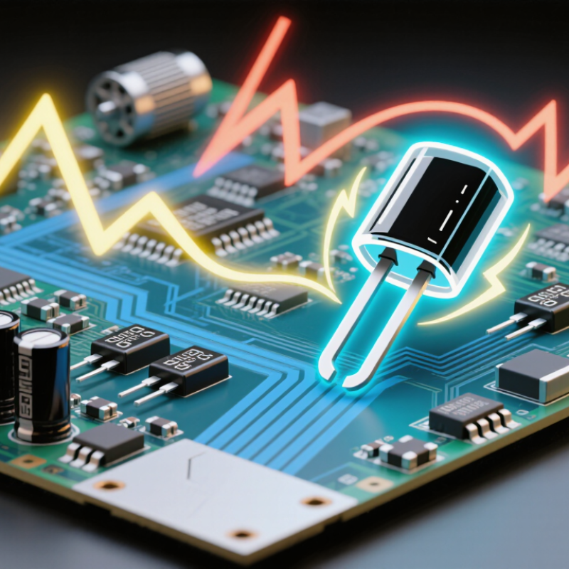
What Is TVS Surge Protection and How Does It Work?

What Is TVS Surge Protection and What Is a TVS Diode?

What Is TVS Surge Protection and What Is a TVS Diode?

A transient-voltage-suppression (TVS) diode protects sensitive circuits from short voltage spikes. It normally remains nearly invisible to the circuit. When a surge exceeds its rated standoff voltage, the diode enters avalanche conduction and diverts current away from vulnerable components. Many silicon TVS devices respond within sub-nanosecond timeframes, but speed alone does not guarantee protection. The clamping voltage, peak pulse current, and pulse duration must match the system.

The IEC 61000-4-5 surge-immunity standard uses test levels from 0.5 kV to 4 kV, depending on the equipment environment and coupling method. These values show why component selection cannot rely on voltage labels alone. A TVS diode’s VRWM should exceed the circuit’s normal maximum voltage, while its VC must stay below the protected device’s damage limit. Unidirectional devices suit many DC lines. Bidirectional types often fit AC or differential signal paths. Real boards are less predictable than diagrams; trace inductance and grounding can weaken protection.

Tips: Check VRWM, VBR, VC, IPP, and junction capacitance together. Place the diode close to the connector. Keep surge-current paths short and wide. Do not assume a larger diode is automatically better. Its capacitance may distort high-speed signals, and its pulse rating may describe only one standardized waveform. Recheck the design against IEC 61000-4-5 test conditions and actual field transients.

Why Voltage Surges Occur and How They Damage Electronic Circuits

Voltage surges are brief rises above a circuit’s normal operating voltage. They can come from lightning, switching power supplies, motors, relays, or long cables acting like antennas. A nearby lightning strike may inject energy through mains wiring or communication lines. Even a motor stopping can create a sharp inductive spike.

These events damage circuits through excessive electric stress and heat. A microcontroller designed for 5 volts may fail when its input briefly reaches 20 volts. Semiconductor junctions can puncture, traces can burn, and insulation can weaken without immediate failure. The circuit may keep working, but become less reliable later. Small surges can also corrupt data or cause a sudden reset.

TVS surge protection works by staying mostly inactive during normal voltage. When the voltage exceeds its rated standoff level, the device conducts rapidly and diverts current away from sensitive components. Its clamping voltage limits the remaining spike. Placement matters greatly. The TVS device should sit close to the connector, with short, wide traces leading to a solid ground path. I have seen protection perform poorly when the component was technically correct but physically distant. That detail is easy to overlook. Designers must also check pulse energy, polarity, response time, and coordination with fuses or other protection parts. A TVS device is not magic. It may fail after a severe event, and its ratings require careful interpretation.

How a TVS Device Clamps Excess Voltage

A transient voltage suppressor, or TVS device, protects circuits by diverting sudden excess voltage. Its purpose is simple: clamp the spike before sensitive components absorb it. The real process is more precise.

During normal operation, the TVS remains nearly invisible, drawing minimal current. When a surge exceeds its standoff voltage, the device enters avalanche conduction. Its resistance drops sharply. Surge current then flows through the TVS instead of the protected circuit. The voltage rises only to the specified clamping level. It happens in nanoseconds.

IEC 61000-4-5 testing commonly uses an 8/20 microsecond current waveform and a 1.2/50 microsecond voltage waveform. These figures represent severe, repeatable surge conditions used in immunity testing. IEC 61643-11 also evaluates parameters such as maximum continuous operating voltage, nominal discharge current, and clamping voltage. Engineers compare these values with the circuit’s normal voltage and peak tolerance.

A practical example helps. A 5-volt data line may need a TVS with low capacitance and a carefully selected clamp voltage. A poor choice can distort high-speed signals or fail during repeated surges. Lower clamping is not automatically safer. Layout matters too; every millimeter of trace adds inductance during a fast event. Measurements from a transient test bench often reveal what a schematic hides. The design may look correct, yet the protection path remains too long. That is an uncomfortable lesson.

Key Electrical Specifications of TVS Protection Devices

A TVS diode protects sensitive circuits by clamping sudden voltage spikes. Its key specifications determine whether protection works in real conditions. The first value to check is the stand-off voltage, VRWM. It should exceed the circuit’s normal maximum voltage. Otherwise, the device may conduct during ordinary operation.

Breakdown voltage, VBR, shows when the TVS begins conducting heavily. Clamping voltage, VC, indicates the voltage that reaches the protected load during a specified surge current. Lower VC usually offers better protection, but the rating must match the actual pulse. Peak pulse current, IPP, and peak pulse power define how much surge energy the device can handle. These values depend on the test waveform, often 8/20 microseconds. A larger number is not automatically safer.

Leakage current matters in battery-powered equipment. High leakage can slowly drain a small battery. Capacitance also deserves attention, especially on high-speed data lines. Excessive capacitance may distort signal edges and increase insertion loss. Response time is normally extremely short, but layout can weaken performance. Short traces, a solid ground path, and suitable copper width reduce unwanted inductance. Testing on a bench has taught me that a theoretically correct part can still clamp too late. Surge repetition, temperature, and mounting space can change the result. Specifications are useful, but they are not the whole design.

How to Select and Install the Right TVS Surge Protector

Selecting a TVS surge protector starts with the circuit’s normal operating voltage. Choose a standoff voltage above the highest continuous voltage. Its breakdown voltage must still protect sensitive components.

Check the clamping voltage at the expected surge current. Compare peak pulse power with the real transient waveform, not only the load current. A unidirectional device suits many DC rails. A bidirectional device usually fits AC lines and differential signals.

High-speed interfaces also need low capacitance. Otherwise, protection may distort useful signals. Package size, thermal limits, and applicable safety requirements deserve careful review. Datasheet values can vary with temperature and pulse duration. That detail is easy to miss.

Install the TVS device in parallel with the protected line, close to the connector or entry point. Keep the surge path short, wide, and direct. Long, narrow traces add inductance and reduce protection performance.

Connect the return path to a low-impedance ground or designated chassis point. Avoid routing protected traces beside the surge current path. Add suitable fusing when a failed TVS could create excessive current.

During bench testing, measure the clamping voltage with a short ground connection. A long probe lead can create misleading spikes. In practice, an initial layout may pass a basic test yet fail during a faster transient. Recheck spacing, grounding, and heat after enclosure assembly. Noise, vibration, and moisture can expose weaknesses that laboratory testing misses.

Get In Touch

Drop Us A Message

    Our Contact Details

    • IPS Group BV | Head Office (NB), Technopol 4, 5026 SB Tilburg, The Netherlands

      IPS Group BV | Rhijnspoor 239, 2901 LB Capelle a/d IJssel, The Netherlands
    • sale@qbhardware.org
    • +31 (0) 10 303 2625